Controls
The planned control system combines temperature regulation, airflow control, instrumentation, and supervised operating states for the HELIOS forge.
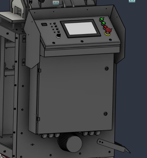
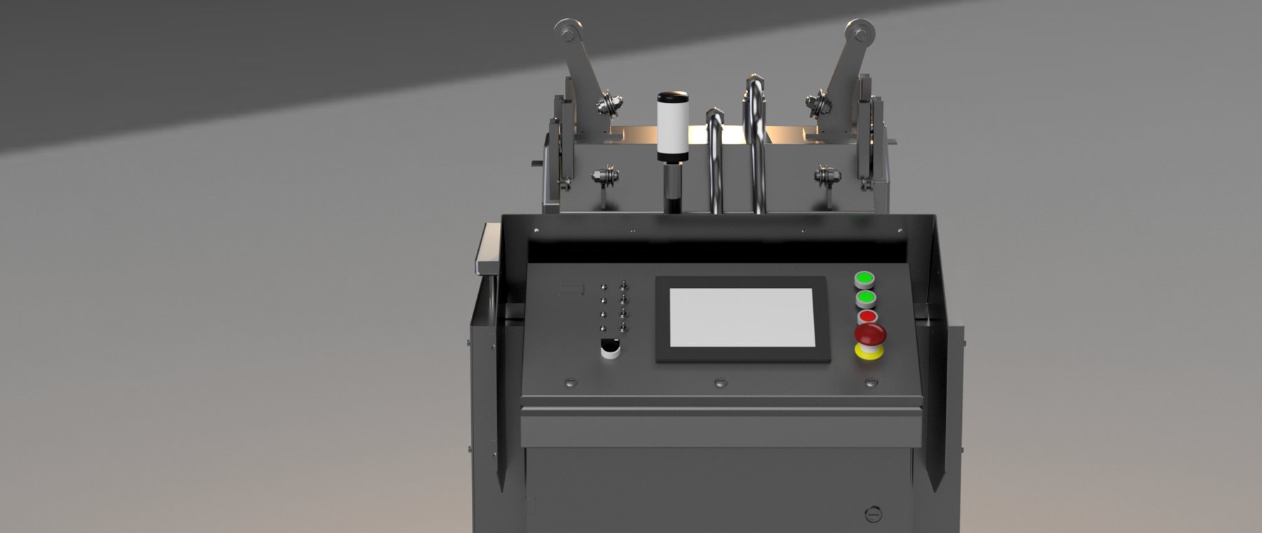
Control architecture
The Phoenix Contact PLCnext architecture discussed for HELIOS separates routine process control from safety-related control. The standard PLC handles temperature regulation, blower-speed requests, the HMI, and logging. A dedicated safety-control layer supervises the conditions that permit firing and commands fuel shutdown when those conditions are lost. This page describes the intended architecture; the final implementation and commissioning results are still to be documented.
Temperature control
A thermocouple measures the forge temperature and supplies feedback to the controller. The temperature-control loop compares that measurement with the operator’s setpoint and adjusts the requested heat input. Blower speed is the main modulating output: the PLC commands the VFD, and the VFD changes the blower motor speed. The actual control response depends on the forge’s thermal inertia, sensor placement, and tuning.
Airflow and fuel mixture
The blower supplies motive air to the proportional air mixer. A change in airflow changes the venturi suction and the amount of propane entrained through the adjusted choke. The intended result is coordinated air and fuel modulation without continuously repositioning the manual mixture trim. The HMI temperature setting therefore changes the heat request; it does not directly reposition the mechanical choke.
Instrumentation
The design discussions included thermocouples, airflow or differential-pressure measurement, flame detection, and gas-pressure supervision. These signals serve different purposes: process measurements support regulation and diagnostics, while dedicated proving and limit devices support the safety-control functions. A separate excess-temperature limit is intended to provide protection independently of the normal temperature-control loop.
Operating sequence
The intended operating states are idle, pre-start checks, purge, ignition, flame proving, firing, normal shutdown, and lockout. The safety-control sequence determines whether the conditions for progressing to the next state are satisfied. During firing, the temperature controller can request more or less heat only while the required permissions remain valid. Timing values, interlock details, and validation records are implementation work rather than claims of completed testing.
Faults and shutdown
Loss of required airflow, loss of flame, an excessive-temperature condition, a gas-pressure fault, or an emergency stop is intended to remove permission to fire and close the fuel shutoff valves through the safety-control path. Fault handling must distinguish a normal stop from a lockout that needs investigation and deliberate reset. The HMI reports these states; the screen itself is not the safety shutdown mechanism.
Logging and maintenance
The planned software includes operating-hour and cycle tracking, fault history, equipment health checks, and maintenance reminders. These records are intended to support teaching-lab use by making recurring issues and service requirements easier to identify. They remain planned functions until implemented and tested.